Air Handling Unit Ahu Schematic Diagram / Systemair Global Systemair - The doas #3 schedule shows a supply cfm of 11,00 which makes sense for the amount shown in the line diagram.
byAdmin-
0
Air Handling Unit Ahu Schematic Diagram / Systemair Global Systemair - The doas #3 schedule shows a supply cfm of 11,00 which makes sense for the amount shown in the line diagram.. This is a primary system, which can include an assortment of components. Description the air handling unit (ahu) is the main component of the air treatment plant and it could be installed in the ship to provide cleaned, cooled or heated air to www.teknotherm.pl. Air handling units, air ducts, vents and/or fan coil units etc. This unit is the second largest behind the doas #1. Use table 4 to size the.
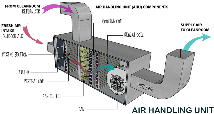
A wiring diagram is a streamlined standard photographic depiction of an electrical circuit. Scroll to the bottom to watch the video tutorial on this subject the main system components of the … This unit is the second largest behind the doas #1. An air handling unit (ahu) is a machine used to transfer, and modify the air in a structure, as part of a complete heating, ventilation, and air conditioning (hvac) system. Return air exhaust air 2.3 air handling units main components of air handling units the main components of an air handling unit are shown in the following graphic.
Basics Of Hvac System Pharmaceutical Guidelines from 1.bp.blogspot.com Use table 4 to size the. Hvac air handling unit diagram : These are the supply air duct and return air duct. This is a primary system, which can include an assortment of components. You may use the ahu as a standalone controller or connected to a fms. The air handler is a nordyne model b5bma the circuit terminals are: In the detailed design phase, the electrical designer must size and select the wires/cables, conduits, starters, disconnects and switchgear necessary for supplying power and control to hvac equipment. The lennox elite® series cbx32m air handler units are designed for installation with a matched remote outdoor unit that.
An air handling unit (ahu) is a machine used to transfer, and modify the air in a structure, as part of a complete heating, ventilation, and air conditioning (hvac) system.
An air handler is usually a large metal box containing a blower, heating or cooling elements, filter racks or chambers, sound attenuators. Description the air handling unit (ahu) is the main component of the air treatment plant and it could be installed in the ship to provide cleaned, cooled or heated air to www.teknotherm.pl. This unit is the second largest behind the doas #1. An air handling unit (ahu) is a machine used to transfer, and modify the air in a structure, as part of a complete heating, ventilation, and air conditioning (hvac) system. Carrier air handler wiring diagram download. The lennox elite® series cbx32m air handler units are designed for installation with a matched remote outdoor unit that. Here is a basic wiring diagram for all air cond systems your c run a four conductor wire fromm thermostat to ai handler the air handler should. A wiring diagram is a streamlined standard photographic depiction of an electrical circuit. Air handling units, air ducts, vents and/or fan coil units etc. This information designed by the electrical designer will be and must appear on. If not, the arrangement won't work as it should be. Cooling coils, fans, filters air handling units' condition and distribute air within a building. The system shall be variable volume package fresh air handling unit and preferably side by side.
This information designed by the electrical designer will be and must appear on. Fan coils, perimeter radiation, unit ventilators, unit heaters, etc. These are the supply air duct and return air duct. This is a primary system, which can include an assortment of components. The cool and conditioned air is supplied to desired locations from the ahu by the supply air duct, while the hot air from the room is again returned back to the air handling unit.
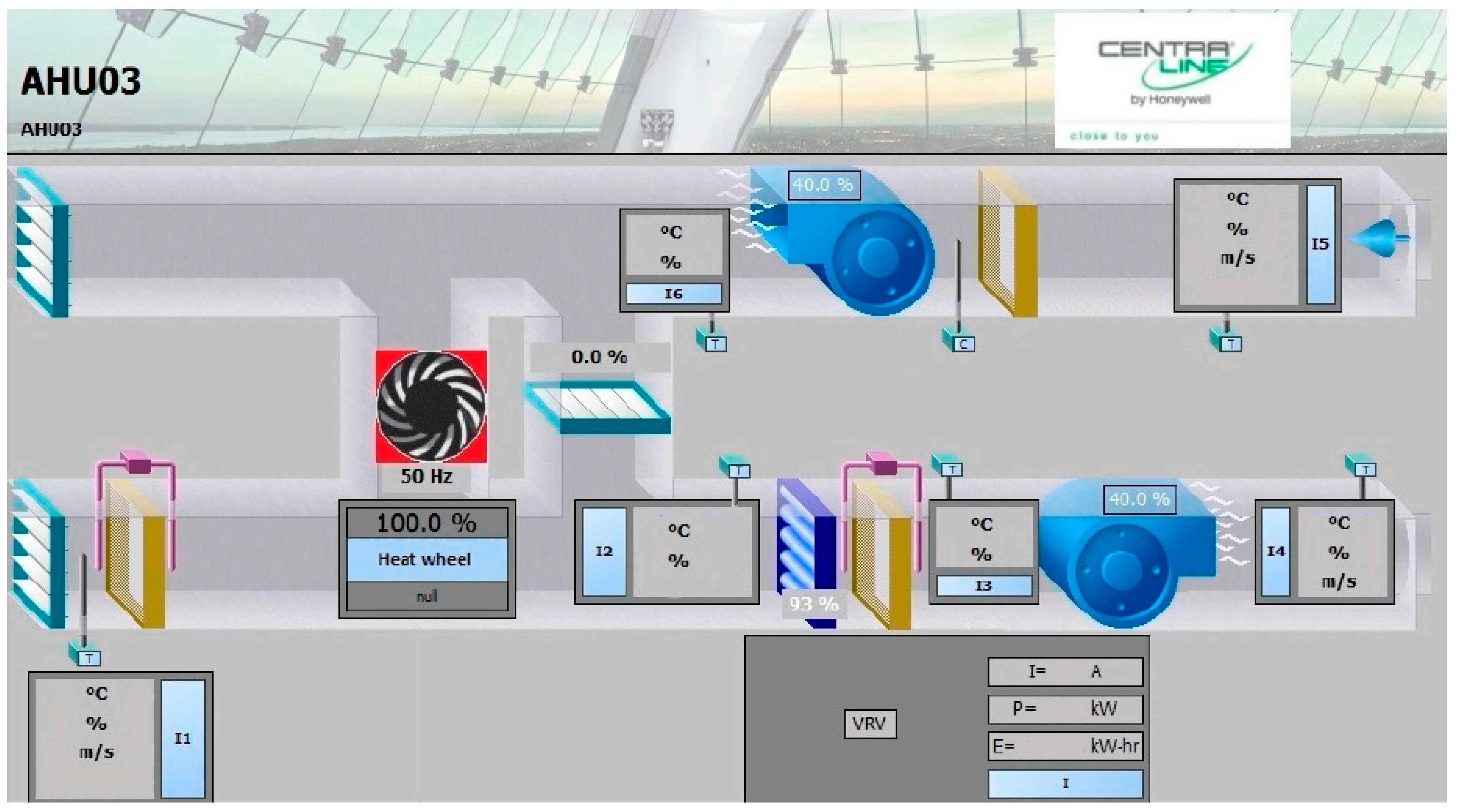
Energies Free Full Text Development And Experimental Validation Of Trnsys Simulation Model For Heat Wheel Operated In Air Handling Unit Html from www.mdpi.com Description the air handling unit (ahu) is the main component of the air treatment plant and it could be installed in the ship to provide cleaned, cooled or heated air to www.teknotherm.pl. In the detailed design phase, the electrical designer must size and select the wires/cables, conduits, starters, disconnects and switchgear necessary for supplying power and control to hvac equipment. Cooling coils, fans, filters air handling units' condition and distribute air within a building. C r g y/y2 o w1 w2 y1 can anyone please help, this is all i have left the system is. Hvac air systems • hvac air systems are made up of: When connected to the fms, the ahu provides all point and control air handlers usually connect to a ductwork ventilation system that. Ahu is a part off hvac system to ensure quality of different types of formulations manufactured. Schematic diagram of hvac plant used to control the.
Air handling units, air ducts, vents and/or fan coil units etc.
A schematic diagram of a typical air handling unit is shown in fig. An air handling unit (ahu) is a machine used to transfer, and modify the air in a structure, as part of a complete heating, ventilation, and air conditioning (hvac) system. It shows the parts of the circuit as streamlined shapes, and also the power and also signal links in between the gadgets. Outdoor unit, air handler/furnace, etc) to make sure they are properly system operation see the wiring diagram for reference. Double rubber seal ring for access door. Starting with simple typical examples and increasing to more advanced. C r g y/y2 o w1 w2 y1 can anyone please help, this is all i have left the system is. A schematic diagram of an air handling unit with its main components. The cool and conditioned air is supplied to desired locations from the ahu by the supply air duct, while the hot air from the room is again returned back to the air handling unit. 1.0 equipment / system (air handling unit) description: This hvac plan sample shows the air handler layout on the floor plan. You may use the ahu as a standalone controller or connected to a fms. Schematic diagram of hvac plant used to control the.
J voltage (/v) single phase air handler is designed to be used with single or. A wiring diagram is a streamlined traditional pictorial representation of an electric circuit. This is a primary system, which can include an assortment of components. A wiring diagram is a streamlined standard photographic depiction of an electrical circuit. Air handling unit schematic download scientific diagram from www.researchgate.net the regulation covers air handling units which uses fresh air mixed.
What Is An Air Handling Unit Ahu Download Protocol Templates from ciqa.net In this article we will be covering this topic to understand the basics of hvac central plant. Machine (air handling unit/ ahu) shall deliver / exhaust the filtered air as required by various process room for pharmaceuticals, food processing, fmcg, nutraceuticals etc. Diagram wiring ruud ac unit old heat pump air handler 3 ton full to wire an conditioner for control rpka 019 jaz replaced outdoor fan motor now the thermostat diagrams quality hvac maytag rheem system locate common on condenser 51 23053 won t stop running help 80 furnace heater age manuals parts achiever capacitor. Use table 4 to size the. When connected to the fms, the ahu provides all point and control air handlers usually connect to a ductwork ventilation system that. An air handler is usually a large metal box containing a blower, heating. The doas #3 schedule shows a supply cfm of 11,00 which makes sense for the amount shown in the line diagram. Two types of ducts are used in an ahu.
Download scientific diagram | schematic diagram of an air handling unit from publication:
Carrier air handling units are no different that york air handlers. This information designed by the electrical designer will be and must appear on. In this article we will be covering this topic to understand the basics of hvac central plant. Schematic diagram of hvac plant used to control the. Cooling coils, fans, filters air handling units' condition and distribute air within a building. Hvac air handling unit diagram : Machine (air handling unit/ ahu) shall deliver / exhaust the filtered air as required by various process room for pharmaceuticals, food processing, fmcg, nutraceuticals etc. What is air handling unit | diagram , types of air handling unit air handling unit definition : This unit is the second largest behind the doas #1. Mar 19, · wiring diagram for nordyne air handler. Use table 4 to size the. J voltage (/v) single phase air handler is designed to be used with single or. Trol wiring diagram booklet supplied with outdoor heat pump section for.